FRR with BFD for route failover via different paths on HP 5820 (Comware5)

HP 5820 (running Comware5 OS) does support fast reroute (FRR) & bidirectional forwarding detection (BFD) feature like Cisco, Juniper and others. Recently I have implemented FRR & BFD with static routes to get route protection/detour to a destination network via different paths on HP5820.

Before come across FRR & BFD – I was looking for a solution that could do tracking of next-hop address in-case of primary link failure and detour the same route through an alternative path using static routes. As the network got multi-vendor devices – a good IGP protocols might not work properly over IPsec VPN tunnel (few latest products does support this although); that’s why I was looking to get this done through static routes. A lot of documents mentioned FRR as a feature of MPLS – this works fine on non-MPLS environment as well.

The next-hope address tracking was done by using BFD (bidirectional forwarding detection) – this is a super fast compared to IGP hello intervals. Default BFD check interval is 50ms. However, BFD is not suitable for slow speed & higher latency network.

Here is the network topology –

FRR-Topology

In this topology –

a. Primary connectivity between Site-A and Site-B is dark optical fiber link – which provides full wire speed.

b. In case optical fiber fail – the Site-A and Site-B connectivity must go through site to site IPsec VPN over the Internet.

The configurations are following –

a. Site-to-site IPsec VPN been established (omitted)

b. IP address configurations have been done on vlan interfaces on both Site-A & Site-B switches (omitted).

c. Configurations on Site-A HP5820-SW01-

#configure BFD (bidirectional forwarding detection) source to track next-hop IP address
bfd echo-source-ip 172.16.10.1

##define the primary route to Site-B via optical fiber – static route
ip route-static 2.2.2.0 255.255.255.0 Vlan-interface10 172.16.10.2

##define Site-B network prefix to be used in the route policy
ip ip-prefix site-b-prefix 10 permit 2.2.2.0 24

##define route-policy to route to Site-B via IPsec VPN as backup route
route-policy site-a-frr permit node 10
   if-match ip-prefix site-b-prefix
   apply fast-reroute backup-interface Vlan-interface20 backup-nexthop 172.16.20.2

##configure the backup next hop static route
ip route-static fast-reroute route-policy site-a-frr

d. Configurations on Site-B HP5820-SW02-

#enable BFD (bidirectional forwarding detection) source to track next-hop IP address
 bfd echo-source-ip 172.16.10.2

##define the primary route to Site-A via optical fiber
ip route-static 1.1.1.0 255.255.255.0 Vlan-interface10 172.16.10.1

##define Site-B network prefix to be used in route policy
ip ip-prefix site-a-prefix 10 permit 1.1.1.0 24

##define route-policy to route to Site-B via IPsec VPN as backup route
route-policy site-b-frr permit node 10
   if-match ip-prefix site-a-prefix
   apply fast-reroute backup-interface Vlan-interface30 backup-nexthop 172.16.30.2

##configure the backup next hop static route
ip route-static fast-reroute route-policy site-b-frr

That’s all for the configurations!

Let’s verify the configuration –
#display bfd session      ;this will display tracking of next-hop

If the state is DOWN – “backup next-hop” will become the active route

BFD-Sessions

#display ip routing-table 2.2.2.0 verbose                             ;on HP5820-SW01

#display ip routing-table 1.1.1.0 verbose                             ;on HP5820-SW02

FRR-RoutingTable

This will display both NextHop and BackupNextHop for the same destination.

Enable SSH on HP ProCurve 6600 series switch

HP ProCurve 6600 runs “ProVision” network operating system. ProVision command syntaxes are pretty much similar to Cisco IOS commands.

Following are commands to enable SSH on a ProCurve 6600 series –

First create local user account on the switch; command is –

#password manager user-name admin; this will prompt to enter password

Generate crypto keys for SSH server; command is –

#crypto key generate ssh

Enable SSH service; command is –

#ip ssh

To check SSH service status, enter the following command –

#show ip ssh

hp-6600-ssh

To restrict access to SSH (or local services on the switch), configure authorised manager IP address; command is –

#ip authorized-managers IP_Address

That’s all.

Adding a new disk ONLINE to a Linux VM running on VMware (no reboot required)

Adding a new disk ONLINE on a virtual Linux server is easy as adding disk to a Windows 2008/2012 Server online! No reboot required.

Make sure the following software already installed on your Linux VM.

-VMware Tools (for other hypervisor install the guest plugin on the VM)

-sg3_utils

-lsscsi

In this example I used RedHat/CentOS running on VMware.

Technical procedures are following –

Before we began let’s see how many disks are currently provisioned on the Linux VM. To do this execute “#lsscsi” command; screenshot –

In this example the server currently have three disks (03) installed.

Linux-VM-Disk-1

Now add a new disk to the VM through vSphere client. Execute the same “#lsscsi” command – the newly disk will not appear!

To get this newly added disk recognized by the Linux system we need to do “rescan SCSI bus”. Usually “SCSI bus” rescan happen every time when the machine gets rebooted – however this time we don’t want to reboot the system!

Execute the following command to rescan “scsi bus” –

# /usr/bin/rescan-scsi-bus.sh -l

(this script is a part of sg3_utils)

You should be able to see the newly added disk on the command output. Screenshot –

Linux-VM-Disk-2

Now if you do a “#lsscsi” this will display four (04) disks. Previously it was three (03) disks in this example.

The new disk information will appear in “dmesg” as well; do a “dmesg | grep disk” to find details.

Next step should be partition the new disk, create file system and provide a mount point; if you want auto mount then add the partition details to “/etc/fstab”.


Configure Perl CPAN to use HTTP mirror instead of FTP – also access mirrors via HTTP Proxy

By default perl CPAN is configured to use FTP mirrors instead of HTTP mirrors.

If your environment only allows HTTP out through http proxy service – this prevents installation of new perl CPAN modules over the internet. I have seen lot of companies they allow access to internet only through http/https proxy server.

In this configure I will show –

(i)how to configure CPAN to use HTTP mirrors instead of FTP.

(ii)how to configure CPAN to use a http proxy server to access HTTP mirrors over the Internet.

Part 1: Configure CPAN to use HTTP mirror instead FTP

i. invoke perl cpan command shell first

#perl –MCPAN –e shell

If you ran CPAN for the first time in a computer – the above command might ask you

Are you ready for manual configuration? [yes]

Enter no.

ii. Set your preferred CPAN HTTP mirror URL

#cpan> o conf urllist push http://www.perl.com/CPAN; you can enter your preferred CPAN mirror URL here.

iii. List and verify your newly entered http mirror

#cpan> o conf urllist       ; this should return the above http mirror URL

iv. Save the new configuration

#cpan> o conf commit

CPAN is ready to use HTTP instead of FTP.

Part 2: Configure CPAN to use a HTTP proxy server to access Internet

i. invoke perl CPAN command shell first

#perl –MCPAN –e shell

If you ran CPAN for the first time in a computer – the above command might ask you

Are you ready for manual configuration? [yes]

Enter no.

ii. Set your HTTP proxy server address, port and auth details

#cpan> o conf init /proxy/

Your ftp proxy?                                 ;nothing to enter here

Your http proxy?myproxy:8080                 ;enter your proxy server IP or hostname with port number

Your proxy user id?                         ; if your proxy use proxy_auth enter username

iii. Save your configuration

#cpan> o conf commit

Your CPAN should be ready to access HTTP mirrors via proxy!

Cisco ASA 5500 series recommended IOS upgrade path

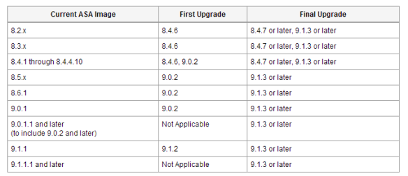
You might encounter problem while attempt to upgrade Cisco Adaptive Security Appliance (ASA) to Version 8.4.7 or later or to Version 9.1.3 or later. Here is below the recommended upgrade path – that resolves the problem.

ASA-firmware

ASA version pre-8.3 NAT rule syntax are different than version 8.4 and later. This upgrade path will automatically convert pre-8.3 version NAT rule syntax to version 8.4 and later.

Few well known errors are “”No Cfg structure found in downloaded image file” and “no NAT rule found after the upgrade”.

HP 5820 LACP (802.3ad) with non-HP (Cisco, F5 and others)

HP 5820-24XG-SFP+ is a 24 port 10GB SFP+ Layer 3 enterprise and carrier grade Ethernet switch. This is running Comware5 network operating system. This switch is actually manufactured by H3C.

HP 5820 series LACP (802.3ad) link aggregation is called “Bridge-Aggregation” interface. The configuration is pretty much similar to Cisco EtherChannel.

I will discuss two things here–

(a). how to configure link-aggregation between HP and non-HP (Cisco, F5, Juniper) devices.

(b). how to configure link-aggregation between HP and HP (HP ProCurve ProVision, Comware5/7, HP SAN).

Following are configuration commands to create LACP between HP and non-HP devices –

(a). Enter the following command on the HP switch to create bridge-aggregation interface

(trunk/tagged vlan interface example)

interface Bridge-Aggregation1
 description “LACP Trunk goes to a non-HP device”
 port link-type trunk
 port trunk permit vlan all ;this can be limited to user define VLANs only 
 link-aggregation mode dynamic  ;for non-HP mode dynamic is require

(access port example)

interface Bridge-Aggregation2
 description “LACP access goes to a non-HP device”
 port access vlan 100
 link-aggregation mode dynamic  ;for non-HP mode dynamic is require

After define bridge aggregation interface – you need to add physical interfaces to it. Physical interface should inherit all the parameters configured on the bridge-aggregation interface.

Make sure physical interfaces are configured with “default” settings only before put them to a bridge-aggregation group to get settings auto inherited. Otherwise you need to specify “link-type” and “permit vlan” parameters once again on all the member physical interfaces.

interface Ten-GigabitEthernet1/0/22
   port link-mode bridge
   description “this interface is a member of bridge-aggregation 1”
   port link-type trunk
   port trunk permit vlan all
   port link-aggregation group 1

interface Ten-GigabitEthernet2/0/22
   port link-mode bridge
   description “this interface is a member of bridge-aggregation 1”
   port link-type trunk
   port trunk permit vlan all
   port link-aggregation group 1

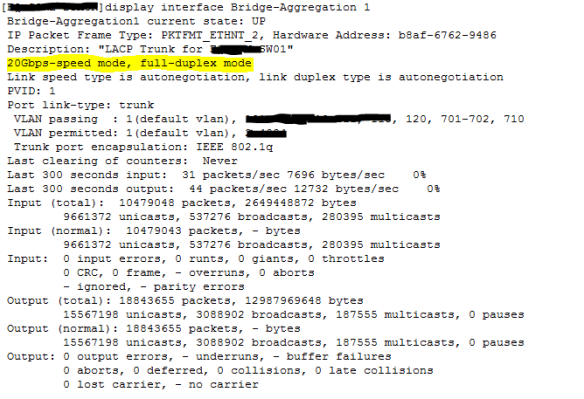
Once done – you should be able to see aggregated bandwidth on the “Bridge-Interface”.

Do a “#display interface Bridge-Aggregation 1

Screenshot of a two 10Gbps LACP interface (20Gbps aggregated) –

5820-LACP

(b). For LACP between HP and HP devices enter all the above commands except “link-aggregation mode dynamic”.

Splunk user authentication with Windows Active Directory

Recently I have implemented Windows Active Directory authentication for Splunk. My Windows AD DS is a mix of Windows 2008 and Windows 2012; Splunk version is 6.x.

Here is below the technical steps-

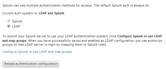
1. Login to Splunk using admin account. Go to “Settings > Access Controls > Authentication method”. You should be able to see the available authentication methods here. Select “LDAP” and click on “Configure Splunk to use LDAP and map groups”. Screenshot –

Splunk-AD-1

2. Click on the “New” button. On the new page – this is the main LDAP strategy configuration settings page. Following are the main AD items that you need to enter here –

a. LDAP connection settings – based on connection settings Splunk will talk to AD.

LDAP strategy name: just a name.

You can have multiple LDAP strategies such as –  (i)strategy one for ready only access through an AD Group mapping to Splunk roles (user & power user), (ii)strategy two for full access through another AD Group mapping to other Splunk roles (Admin, Splunk-system-role) or similar.

Default Splunk roles are – admin, can_delete, power, splunk-system-role, user.

Port number: 389 (this is AD LDAP default)

Connection order: default

Bind DN: cn= AcctName Splunk,ou=yourSvcAcctOU,dc=yourDCName,dc=yourDCExtension

This is distinguished name of your Splunk account that you created in AD. It is recommended you should not use default AD administrator account or your own AD login here. You should create a dedicate account for Splunk – no AD administrative privilege required on this account.

Bind DN Password: enter the password of AD Splunk account

Splunk-AD-2

b. User Settings – Splunk will look for users in AD based on this

User base DN: dc=yourDCName,dc=yourDCextension

User base filter: leave this blank or you can enter specific AD search filter here

User name attribute: samaccountname

Real name attribute: displayname

Group mapping attribute: dn

Screenshot –

Splunk-AD-3

c. Group settings – Splunk will look for AD groups in AD based on this

Group base DN: cn=Group_Splunk_Access_Admins,ou=youGroupOUName,dc=yourDCName,dc=DCextension

This is the AD group that been created to grant access in Splunk.

Static member attribute: member

Screenshot-

Splunk-AD-4

d. Dynamic group settings – optional

e. Advanced settings – default is ok; however you can increase search request size limit.

Screenshot –

Splunk-AD-5

Click on the “Save”. If entered parameters are not correct – you won’t be able to save.

Now you should be able to see your LDAP strategy. Make sure it is enabled.

To see your AD group in Splunk, click on “Map groups”.

To map Splunk role(s) to an AD group – click on “Map groups > AD Group Name > available and selected roles”; screenshots –

Splunk-AD-6

Splunk-AD-8

Also you should be able to see AD users at “Settings > Access controls >Users”. Make sure AD users are member of the Splunk group that been created on AD.

HP ProCurve 6600 series firmware upgrades using USB flash drive

Firmware upgrade on a HP ProCurve 6600 series (24g-4xg or 48g-4xg or 24xg) can be done in several ways, here I will cover upgrading firmware using USB stick.

HP 6600 series always keep two boot images on the flash – (i)primary boot image and (ii)secondary boot image; by default switch boot from the primary. During new firmware upgrade the system automatically take a backup of primary image and copy this to the secondary – so no worry; if you messed up with firmware upgrade you can tell the system to boot from secondary (which is you current good one in fact).

Also firmware upgrade process will keep a backup of your “configurations” in the switch – however it is recommended you should take copy of the same before start upgrade process.

1. Download the latest firmware from HP My Networking site – https://h10145.www1.hp.com/downloads/ProductsList.aspx?lang=&cc=&prodSeriesId=

The latest firmware as of today (June 2014) is K.15.13.0005. The firmware file is a “.swi” extension file. Copy this file onto a USB flash drive (do not put this in a sub directory). Before the upgrade make sure which version is you are currently running; the command is “#show flash” – screenshot –

HP-6600-firmware-1

2. Insert the USB stick to the switch; the switch will automatically mount the USB. Do a “#show flash” to see the firmware file visible on the switch.

3. Once you see the firmware file on the switch – let’s start firmware upgrade process. Copy the firmware file to primary flash. The command and screenshot following –

#copy usb flash K_15_13_0005.swi primary

HP-6600-firmware-2

4. Once the copy is finish make sure your primary flash is showing the latest version; the command is “#show flash” again –

HP-6600-firmware-3

(now primary and secondary version are different)

5. Optional – you might need to tell the switch to boot from the primary image; command is “#boot system flash primary” – screenshot following –

HP-6600-firmware-4

The switch will reboot during firmware upgrade.

Once all above are done – do a “#show flash” to confirm the switch is running with the latest firmware.