Cisco UCS Platform Emulator – UCSPE 3.1(2ePE1)

Cisco UCS Platforms are expensive kit to play with. UCS Platforms are not just a standalone router, switch or a firewall that could easily be emulated on a PC – they are bunch of kits interconnected together to deliver the UCS platform. UCS is not a server – it’s a system or a platform compared to traditional computing; UCS comes with unified (LAN/SAN/FC/FCoE/HBA/others) and stateless computing together.

Cisco has come up with a solution to help engineers to get their hands dirty on UCS Platforms – the solution is called Cisco UCS Platform Emulator (UCSPE). The latest UCSPE is version 3.1(2ePE1). Cisco made UCSPE available to everyone – you only need to have a Cisco login.

The whole UCSPE comes with the following-

i. 2 x Fabric Interconnect (Model: UCS-FI-6332-16UP)
ii. 2 x FEX (Model: Nexus 2348UPQ N2K-C2348UPQ)
iii. 3 x UCS 5108 Chassis with 12 x different model blades
iv. 1 x UCSC C3X60 server (Model: UCSC-C3X60)
v. 7 x UCS C series servers (220/240/460)

The above are enough to emulate a complete decent size UCS Platform!

Yes! you can create bunch of full fledged “Service Profiles” with different configurations settings and applied them to the servers; also you can configure the fabric interconnect ports with different options (LAN uplink/Server uplink/FC/FCoE/NAS/Port Channels etc)

UCSPE comes in “OVA” and “VMware VMX/VMDK” format (in a ZIP file); you can run it on VMware Workstation or Fusion (I use Fusion).

The pre-defined OVA/VMX requires only one (01) vCPU, 1024MB memory and 3 x vNICs.

You need 3 x IP address (could be from DHCP or static) to make it accessible – one IP address is for Fabric Interconnect “A”, second one is for Fabric Interconnect B and the third IP address is the VIP of FI-A and FI-B Cluster.

Thats all! Its a great tool for candidates learning towards CCNA/CCNP/CCIE Data Centre certifications as well.

UCSPE download link is the following:
https://communities.cisco.com/docs/DOC-71877

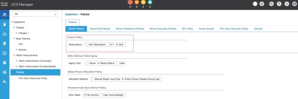
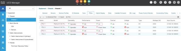
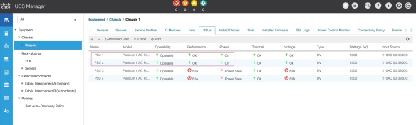
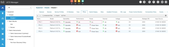
Following are few screenshots:

UCSPE-VM-1

[UCSPE VM console]

UCSPE-Platform-01

[UCSPE devices list. They covered a lot devices in here! The red arrow is showing the icon of UCSM – you need to click on this to launch UCSM]

UCSPE-Platform-02

[UCSM – Login Screen]

UCSPE-Platform-Topology-01

[UCSM- The Topology]

UCSPE-Platform-Fabric-A-01

[UCSM- FI “A”]

UCSPE-Platform-01-5108-Chassis

[UCSM – UCS 5108 Chassis]


Cisco UCS 5108 Chassis Power Policy Options and Redundancy Demystify

Cisco UCS server chassis 5108 comes with three (03) different Power Policy options; UCS power management is efficient and energy saving by default but NONE of the policy option explanation says which PSUs will be full ON and which PSUs will be put on to Power Saving Mode. This is what official Cisco document says about these options:

  • Non Redundant – All installed power supplies are turned on and the load is evenly balanced. Only smaller configurations (requiring less than 2500W) can be powered by a single power supply.
  • N+1 – The total number of power supplies to satisfy non-redundancy, plus one additional power supply for redundancy, are turned on and equally share the power load for the chassis. If any additional power supplies are installed, Cisco UCS Manager sets them to a “turned-off” state.
  • Grid – Two power sources are turned on, or the chassis requires greater than N+1 redundancy. If one source fails (which causes a loss of power to one or two power supplies), the surviving power supplies on the other power circuit continue to provide power to the chassis.

Probably the above definition applied to old version UCS and not the latest. Also I couldn’t find details on what exactly happen on power redundancy when you have 2 x PSUs and 4 x PSUs installed and your power load is not very high due to not all the blades are installed and functional.

Cisco-UCS-PowerPolicy-1

Following are what I captured regarding which PSUs will be ON and PSUs will be put on to Power-Saving-Mode when you set different “Power Policy” options – this is done a four (04) PSU server chassis. Changing in Power Policy takes effect immediately (might be a 10-20 second delay to refresh the Web GUI) and it doesn’t require any system reboot.

Assumption is all the four (04) PSUs are installed and connected to power socket; also the chassis is running 2 blades.

When Power Policy is set N+1, this is what happen:

PSU1 – ON
PSU2 – ON
PSU3 – OFF (Power Saving Mode)
PSU4 – OFF (Power Saving Mode)

When Power Policy is set GRID, this is what happen:

PSU1 – ON
PSU2 – OFF (Power Saving Mode)
PSU3 – ON
PSU4 – OFF (Power Saving Mode)

When Power Policy is set Non-Redundant, this is what happen (only one is ON! not ALL):

PSU1 – ON
PSU2 – OFF (Power Saving Mode)
PSU3 – OFF (Power Saving Mode)
PSU4 – OFF (Power Saving Mode)

Data centre racks are equipped with two power rails – A (left hand side) & B (right hand side) for redundancy. Now interesting thing is – your physical power connection must be in-line with the UCS Power Policy options, otherwise your blades will be rebooted in case any power issue on “power rail A”.

You can have only two different combinations of power connections to connect all the four (04) PSUs to the power rails A & B. The combinations are following –

Option 1:
PSU1/PSU2 (first two) connected to > power rail A
PSU3/PSU4 (last two) connected to > power rail B

Option 2:
PSU1/PSU3 (odd numbers) connected to > power rail A
PSU2/PSU4 (even numbers) connected to > power rail B

I had N+1 configured with “Option 1” and power issue due to maintenance on rail A rebooted my blades!

This is what happen as following – either “you are saved” during a power failure on rail A! or “you are not saved!

GRID Mode with (Option 1) PSU1/PSU2 to A & PSU3/PSU4 to B;You are saved!
PSU1 – A ON
PSU2 – A OFF (Power Saving Mode)
PSU3 – B ON
PSU4 – B OFF (Power Saving Mode)

GRID Mode with (Option 2) PSU1/PSU3 to A & PSU2/PSU4 to B;You are NOT saved
PSU1 – A ON
PSU2 – B OFF (Power Saving Mode)
PSU3 – A ON
PSU4 – B OFF (Power Saving Mode)

Screenshot of GRID mode following –

Cisco-UCS-PSU-GRID-Pic1

N+1 Mode (Option 1) PSU1/PSU2 to A & PSU3/PSU4 to B;You are NOT saved!
PSU1 – A ON
PSU2 – A ON
PSU3 – B OFF (Power Saving Mode)
PSU4 – B OFF (Power Saving Mode)

N+1 Mode (Option 2) PSU1/PSU3 to A and PSU2/PSU4 to B;You are saved!
PSU1 – A ON
PSU2 – B ON
PSU3 – A OFF (Power Saving Mode)
PSU4 – B OFF (Power Saving Mode)

Screenshot of N+1 mode following –

Cisco-UCS-PSU-N1-Pic1

Non-Redundant Mode (Option 1) PSU1/PSU2 to A & PSU3/PSU4 to B;NOT saved!
PSU1 – A ON
PSU2 – A OFF (Power Saving Mode)
PSU3 – B OFF (Power Saving Mode)
PSU4 – B OFF (Power Saving Mode)

Non-Redundant Mode (Option 2) PSU1/PSU3 to A & PSU2/PSU4 to B;NOT saved!
PSU1 – A ON
PSU2 – B OFF (Power Saving Mode)
PSU3 – A OFF (Power Saving Mode)
PSU4 – B OFF (Power Saving Mode)

Screenshot of Non Redundant mode following –

Cisco-UCS-PSU-NonRedundant-1.jpg