
I found too many reference docs on VXLAN, most of them cover early solutions that do not use MP-BGP EVPN and manage advertisement of BUM traffic (broadcast, unknown unicast and multicast) via multicast. I know people who do not want to run mcast in their network!
Here, I focus on VXLAN with MP-BGP EVPN with ingress replication to manage BUM traffic (VXLAN + MPBGP EVPN + Ingress Replication).
So, What Is “Ingress Replication” Compared To “Multicast” Based VXLAN Solution?
The answer is – ingress replication is called head-end-replication which performs unicast delivery of VXLAN encapsulated packet across remote VTEPs. Unicast replication requires a source VTEP to delivery same data to every single remote VTEPs in “one-to-one” fashion – whereas in multicast a rendezvous point (preferred is PIM-SM RP) defined where all the VTEPs join to receive delivery of VXLAN encapsulated data in “one-to-many” fashion. Multicast has lower overhead and can provide faster delivery compared to unicast; however, multicast is less secure.
MP-BGP EVPN is the next generation solution becoming widely popular in Data Center networks (VXLAN EVPN) and Service Provider networks (MPLS PBB-EVPN).
My plan is to create following step-by-step reference documents for VXLAN EVPN with ingress replication.
- VXLAN, MBGP EVPN with ingress replication – Part 1 – Basic Facts, Design Considerations and Security
- VXLAN, MBGP EVPN with ingress replication – Part 2 – Configure VXLAN on a single POD – L2 VNI – here
- VXLAN, MBGP EVPN with ingress replication – Part 3 – Configure VXLAN on multi PODs – L2 VNI
- VXLAN, MBGP EVPN with ingress replication – Part 4 – Configure VXLAN on multi PODs – L3 VNI
- VXLAN, MBGP EVPN with ingress replication – Part 5 – Configure VXLAN on multi PODs including a collapsed POD besides Spine and Leaf PODs
This is the Part 1.
Let’s Get Some Basic Facts About VXLAN
- the initial specification of VXLAN described in RFC 7348; this describes the need for overlay networks within virtualized data centers accommodating high density tenants (4096++) as traditional VLAN based segmentation can go max up to 4096
- so based on RFC7348, VXLAN is the solution to get rid of classical ethernet (CE) in a data center and extend VLAN boundaries from 4096 to above; ah! NO more VLAN and STP!
- similar alternative are TRILL, NVGRE, Cisco OTV; however, none are widely accepted except VXLAN
- VXLAN header size is 8-byte; this includes a layer 2 virtual network identifier (VNI), which is 24-bit long
- VNI represents a broadcast domain; traditional VLANs are associated with a unique VNI number; you often see the term “bridge-domain” which are in a sense similar to VLANs (or multiple VLAN/subnets of a tenent); a VNI can represent a bridge-domain
- since maximum number of IEEE 802.1Q VLAN is 4096 – you can have max 4096 VNIs per POD (point of delivery); yes – you sill use VLANs for segregation!
- in a large DC environment, you have multiple PODs inter-connected together per data center or across multiple data centers; thus you can have a high density multi-tenancy network that goes beyond 4096! Here you need VXLAN VNIs that gives you segments up to 24-bit (16,777,216 unique network segments in decimal)
- so, VLANs are still there! ah! YES, they are! but VLANs are now local to per POD and/or per switch only; VLAN extension to intra-switches and intra-PODs are done via VXLAN VNIs; switch-to-switch connections are L3 for VXLAN instead of L2 in a typical VLAN based network
- VXLAN use UDP instead of TCP and use port number 4789
- L3 connectivity leverage equal cost multi-paths (ECMP) and use all inter-connect links that provide max throughput and redundancy compared to L2 STP that do not forward traffic over all links because of STP block ports
- since VXLAN header size is 8-byte; VXLAN adds extra overhead to traditional 1500 MTU; VXLAN MTU size is “1500 payload with original IP header + 14 byte Ethernet header + 8 byte VXLAN header + 8 byte UDP header + 8 byte IP header”
- in a real world – VXLAN deployments are done on 9K MTU size end-to-end; none use 1500 MTU
- VXLAN requires end-to-end L3 reachability in the underlay network; underlay reachability is done via IGP, most cases OSPF or IS-IS
- VXLAN encapsulate MAC address into IP packet and transport over L3 network
- VXLAN is the “overlay networking” that runs on the top of underlay that use local “VXLAN Tunnel End Point – VTEP” interfaces to encapsulate packages into VXLAN
- VTEP is the interface where VXLAN traffic encapsulation and de-encapsulation happen (origination and termination of VXLAN traffic)
- VTEP can be hardware based – which is a dedicated network device capable of encapsulation and de-encapsulation of VXLAN packets; Cisco Nexus/Juniper QFX/Arista are good example
- VTEP can be software based – VXLAN encapsulation and de-encapsulation happen on software based virtual network appliance within a virtualization “hypervisor servers”; underlaying physical network is totally unaware of VXLAN; VMware NSX is an example of software based VXLAN VTEP
- software based VTEP handles only traffic those traverse via the hypervisor host machine; whereas hardware based VTEP can handle VXLAN traffic in a much broader space
- VXLAN EVPN involves a “control plane” that handle the MAC address learning (BUM traffic)
- VXLAN EVPN support “ARP suppression” which can reduce arp flood for “silent” hosts/clients (most hosts send GARP/RARP to the network when they come online; silent hosts dont do that)
- VXLAN L3VNI requires “anycast gateway” on the Leaf switches which has a shared IP address across all the participating Leaf switches; very similar to other FHRP (VRRP/HSRP/etc…)
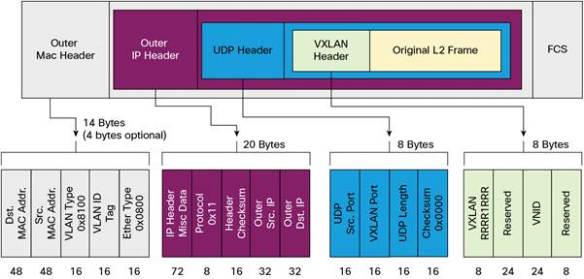
(VXLAN header details – picture copied from cisco.com)
Security in VXLAN MP-BGP EVPN based VTEP
- previous multicast based VTEP peer discovery didn’t have a mechanism or a method for authenticating VTEP peers; in plain English there was “NO” whitelist for VTEP peers!
- the above limitations present major security risks in real-world VXLAN deployments because it allows insertion of a rogue VTEP into a VNI segment!
- if a rogue VTEP has been inserted into the segment, it can send and receive VXLAN traffic! ah! goccha!
- MP-BGP EVPN based VTEP peers are pre-authenticated and whitelisted by BGP; BGP sessions must be established first for a VTEP device to discover remote VTEP peers
- in addition to an established BGP session requirements – BGP session authentication can be added to BGP peers (MD5 3DES)
- in addition to BGP session security – IGP security (aka. auth) can be added to the “underlay” routing protocols
Few Quick Notes on VXLAN Network Design
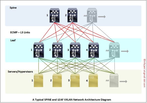
- VXLAN network design doesn’t follow traditional “three layers” network design approach (core – dist – access)
- VXLAN network design typically has two tiers – Spine and Leaf; this design can grow horizontally “pay as you go”; you can add more Spine and Leaf anytime! No more fixed number of switch ports per POD!
- you can have “super spine” on the top of Spine switches
- Leaf switches are connected to Spine switches within the same POD
- Spine to Spine direct network connections are “not” necessary but they “can be” connected
- underlay IGP ensure end-to-end L3 connectivity within Leaf and Spine switches
- clients are connected to the Leaf switches (servers, hypervisors, routers etc…)
- in a multi-POD DC scenario – Spine switches need to be inter-connected (same EVPN control plane across multi-POD); intra-site DCI
- in a multi-site data centre inter-connect (DCI) scenario “segmented” VXLAN “control plane” are deployed to minimise BUM per data center; inter-DC traffic are handled by VXLAN Border Gateway (BGW) routers
- in a multi-site DCI scenario, the Border Gateway router (BGW) can be configured on the Spine switches (there are many other connectivity model/scenarios available for BGW); in this case Spine DC-x to Spine DC-y are connected back to back over via L3 link which is very similar to multi-POD Spine to Spine connectivity
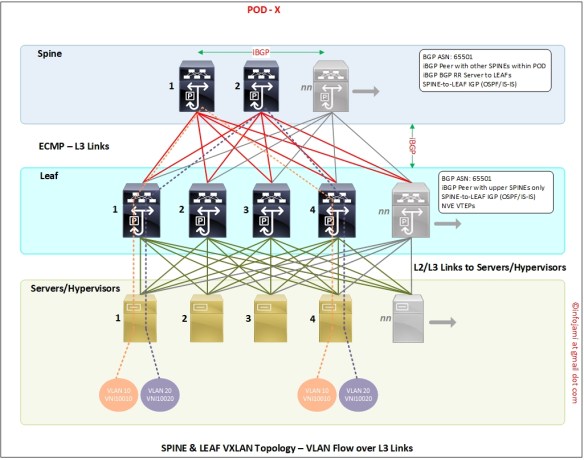
VXLAN traffic flow diagram – inter-switch VLAN traffic follow L3 path.
Few Notes While Configuring VXLAN on Cisco Nexus NXOS
- VXLAN EVPN is based on MP-BGP; this is just an extension to MP-BGP which is very similar to MPLS VPNV4 or VPLS l2vpn
- if you have configured MP-BGP MPLS before – you will find VXLAN EVPN configuration is super easy
- VXLAN VTEP switches are much like “PE” router in a typical MPLS network
