Cisco Nexus vPC and non-vPC VLANs together on the same platform (Nexus hybrid setup) – NXOS v7.0(3)4(1)

Cisco discontinued “spanning-tree pseudo-information” starting from NXOS version 7.0(3)4(1) on the 9000 platforms. So what is the solution for Nexus vPC and non-vPC VLANS on the same platform (hybrid)? Is it no longer going to be supported on NXOS/9000 platforms?

Although hybrid is not recommended vPC design for “aggregation layer” but you find a lot scenarios where you need to have both vPC and non-vPC within the same platform (mostly in mid-size data centres; where you have a lot reasons you can’t deploy traditional ethernet switches; hence you have considered the Cisco Nexus platforms).

If you carry everything (both vPC VLANs and non-vPC VLANs) over the vPC peer-links (yes, vPC carry orphaned VLANs as well!) – in this case if there is any issue happen on the vPC peer links and that stops the vPC working, the downstream switches those are connected to the Nexus via non-vPC/non-vPC VLANs will stop forwarding frames due to STP (any STP – STP/RSTP/PVSTP/MSTP) blockage as they don’t have any information about what happened between the vPC peer Nexus switches in a vPC peer failed scenario.

Experts suggest that you should have an additional Layer 2 trunk port-channel alongside your vPC peer-link; this Layer 2 port-channel will carry non-vPC VLANs in case vPC stops working (whatever reason; could be a Nexus reboot during maintenance!).

Well, now you have setup a seperate Layer 2 trunk port channel for non-vPC VLANs and shutdown the vPC peer link to test it – but you found it is still not working as expected! STP is blocking the Layer 2 trunk link, whats the problem! Cisco used to have a solution for this called “spanning-tree pseudo-information“; as I have mentioned in the beginning Cisco discontinued this starting from version 7.0(3)l4(1) on the Nexus 9000 platform. So what is your option for this? Should you stop using Nexus if you don’t follow spine and leaf design?

Yes – there is an answer to this, there is a small trick to make this working! By discontinuing psuedo-information, Cisco basically makes it ever easier to configure; you need to do the following –

i. First, you need to set STP root priority for the VLANs to a lower priority number on one of Nexus switch (default priority is 32768, lower is prefer; this should be done on the primary vPC role Nexus switch) and leave STP untouched on the other Nexus switch (this is the vPC secondary role switch).

ii. Second, on the non-vPC trunk port-channel set “spanning-tree port type normal” on “both” the switches; (“spanning-tree port type network” is recommended for vPC peer-link).

Here is an example config -Here is an example config –

On the vPC primary role switch, apply the following -

(config)#spanning-tree vlan 10,20,30,40-50 priority 8192

On both the switches, apply the following -

(config)#interface port-channel10
(config-if)#description "non-vPC trunk port" 
(config-if)#switchport 
(config-if)#switchport mode trunk 
(config-if)#switchport trunk allowed vlan 10,20,30,40-50 
(config-if)#spanning-tree port type normal

Without having the above configuration applied you will find STP is blocking the non-vPC Layer 2 trunk link even if the vPC peer-link is shutdown. Also in this example – the vPC primary role switch will be the STP “root bridge” because of lower priority configured (8192).

To test your configuration – shutdown the vPC peer-link, run “show spanning-tree vlan xxx” – you should see STP put the L2 trunk interfaces in forwarding state immediately.

Here is a vPC and non-vPC VLANs on the same platform diagram –

CiscoNexus-Hybrid


Cisco UCS Platform Emulator – UCSPE 3.1(2ePE1)

Cisco UCS Platforms are expensive kit to play with. UCS Platforms are not just a standalone router, switch or a firewall that could easily be emulated on a PC – they are bunch of kits interconnected together to deliver the UCS platform. UCS is not a server – it’s a system or a platform compared to traditional computing; UCS comes with unified (LAN/SAN/FC/FCoE/HBA/others) and stateless computing together.

Cisco has come up with a solution to help engineers to get their hands dirty on UCS Platforms – the solution is called Cisco UCS Platform Emulator (UCSPE). The latest UCSPE is version 3.1(2ePE1). Cisco made UCSPE available to everyone – you only need to have a Cisco login.

The whole UCSPE comes with the following-

i. 2 x Fabric Interconnect (Model: UCS-FI-6332-16UP)
ii. 2 x FEX (Model: Nexus 2348UPQ N2K-C2348UPQ)
iii. 3 x UCS 5108 Chassis with 12 x different model blades
iv. 1 x UCSC C3X60 server (Model: UCSC-C3X60)
v. 7 x UCS C series servers (220/240/460)

The above are enough to emulate a complete decent size UCS Platform!

Yes! you can create bunch of full fledged “Service Profiles” with different configurations settings and applied them to the servers; also you can configure the fabric interconnect ports with different options (LAN uplink/Server uplink/FC/FCoE/NAS/Port Channels etc)

UCSPE comes in “OVA” and “VMware VMX/VMDK” format (in a ZIP file); you can run it on VMware Workstation or Fusion (I use Fusion).

The pre-defined OVA/VMX requires only one (01) vCPU, 1024MB memory and 3 x vNICs.

You need 3 x IP address (could be from DHCP or static) to make it accessible – one IP address is for Fabric Interconnect “A”, second one is for Fabric Interconnect B and the third IP address is the VIP of FI-A and FI-B Cluster.

Thats all! Its a great tool for candidates learning towards CCNA/CCNP/CCIE Data Centre certifications as well.

UCSPE download link is the following:
https://communities.cisco.com/docs/DOC-71877

Following are few screenshots:

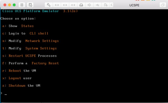
UCSPE-VM-1

[UCSPE VM console]

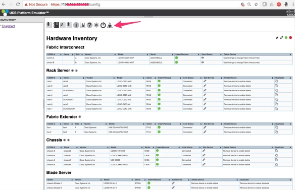
UCSPE-Platform-01

[UCSPE devices list. They covered a lot devices in here! The red arrow is showing the icon of UCSM – you need to click on this to launch UCSM]

UCSPE-Platform-02

[UCSM – Login Screen]

UCSPE-Platform-Topology-01

[UCSM- The Topology]

UCSPE-Platform-Fabric-A-01

[UCSM- FI “A”]

UCSPE-Platform-01-5108-Chassis

[UCSM – UCS 5108 Chassis]


Cisco UCS 5108 Chassis Power Policy Options and Redundancy Demystify

Cisco UCS server chassis 5108 comes with three (03) different Power Policy options; UCS power management is efficient and energy saving by default but NONE of the policy option explanation says which PSUs will be full ON and which PSUs will be put on to Power Saving Mode. This is what official Cisco document says about these options:

  • Non Redundant – All installed power supplies are turned on and the load is evenly balanced. Only smaller configurations (requiring less than 2500W) can be powered by a single power supply.
  • N+1 – The total number of power supplies to satisfy non-redundancy, plus one additional power supply for redundancy, are turned on and equally share the power load for the chassis. If any additional power supplies are installed, Cisco UCS Manager sets them to a “turned-off” state.
  • Grid – Two power sources are turned on, or the chassis requires greater than N+1 redundancy. If one source fails (which causes a loss of power to one or two power supplies), the surviving power supplies on the other power circuit continue to provide power to the chassis.

Probably the above definition applied to old version UCS and not the latest. Also I couldn’t find details on what exactly happen on power redundancy when you have 2 x PSUs and 4 x PSUs installed and your power load is not very high due to not all the blades are installed and functional.

Cisco-UCS-PowerPolicy-1

Following are what I captured regarding which PSUs will be ON and PSUs will be put on to Power-Saving-Mode when you set different “Power Policy” options – this is done a four (04) PSU server chassis. Changing in Power Policy takes effect immediately (might be a 10-20 second delay to refresh the Web GUI) and it doesn’t require any system reboot.

Assumption is all the four (04) PSUs are installed and connected to power socket; also the chassis is running 2 blades.

When Power Policy is set N+1, this is what happen:

PSU1 – ON
PSU2 – ON
PSU3 – OFF (Power Saving Mode)
PSU4 – OFF (Power Saving Mode)

When Power Policy is set GRID, this is what happen:

PSU1 – ON
PSU2 – OFF (Power Saving Mode)
PSU3 – ON
PSU4 – OFF (Power Saving Mode)

When Power Policy is set Non-Redundant, this is what happen (only one is ON! not ALL):

PSU1 – ON
PSU2 – OFF (Power Saving Mode)
PSU3 – OFF (Power Saving Mode)
PSU4 – OFF (Power Saving Mode)

Data centre racks are equipped with two power rails – A (left hand side) & B (right hand side) for redundancy. Now interesting thing is – your physical power connection must be in-line with the UCS Power Policy options, otherwise your blades will be rebooted in case any power issue on “power rail A”.

You can have only two different combinations of power connections to connect all the four (04) PSUs to the power rails A & B. The combinations are following –

Option 1:
PSU1/PSU2 (first two) connected to > power rail A
PSU3/PSU4 (last two) connected to > power rail B

Option 2:
PSU1/PSU3 (odd numbers) connected to > power rail A
PSU2/PSU4 (even numbers) connected to > power rail B

I had N+1 configured with “Option 1” and power issue due to maintenance on rail A rebooted my blades!

This is what happen as following – either “you are saved” during a power failure on rail A! or “you are not saved!

GRID Mode with (Option 1) PSU1/PSU2 to A & PSU3/PSU4 to B;You are saved!
PSU1 – A ON
PSU2 – A OFF (Power Saving Mode)
PSU3 – B ON
PSU4 – B OFF (Power Saving Mode)

GRID Mode with (Option 2) PSU1/PSU3 to A & PSU2/PSU4 to B;You are NOT saved
PSU1 – A ON
PSU2 – B OFF (Power Saving Mode)
PSU3 – A ON
PSU4 – B OFF (Power Saving Mode)

Screenshot of GRID mode following –

Cisco-UCS-PSU-GRID-Pic1

N+1 Mode (Option 1) PSU1/PSU2 to A & PSU3/PSU4 to B;You are NOT saved!
PSU1 – A ON
PSU2 – A ON
PSU3 – B OFF (Power Saving Mode)
PSU4 – B OFF (Power Saving Mode)

N+1 Mode (Option 2) PSU1/PSU3 to A and PSU2/PSU4 to B;You are saved!
PSU1 – A ON
PSU2 – B ON
PSU3 – A OFF (Power Saving Mode)
PSU4 – B OFF (Power Saving Mode)

Screenshot of N+1 mode following –

Cisco-UCS-PSU-N1-Pic1

Non-Redundant Mode (Option 1) PSU1/PSU2 to A & PSU3/PSU4 to B;NOT saved!
PSU1 – A ON
PSU2 – A OFF (Power Saving Mode)
PSU3 – B OFF (Power Saving Mode)
PSU4 – B OFF (Power Saving Mode)

Non-Redundant Mode (Option 2) PSU1/PSU3 to A & PSU2/PSU4 to B;NOT saved!
PSU1 – A ON
PSU2 – B OFF (Power Saving Mode)
PSU3 – A OFF (Power Saving Mode)
PSU4 – B OFF (Power Saving Mode)

Screenshot of Non Redundant mode following –

Cisco-UCS-PSU-NonRedundant-1.jpg

Ubiquiti UniFi @ My Home

I have been using Ubiquiti UniFi solutions last 10 months at my home NBN and wireless network – so far a happy customer; I should have got this solution even earlier! I tried few high-end dual-band wireless modems with triple MIMO antennas and with AC connection speed – Ubiquiti UniFi solutions are heaps better than those.

Although Ubiquiti UniFi solutions are not labelled suitable for “home users” – but they are not too hard to setup. I brought at least a dozen UniFi home customers to Uniquiti – they should send me free UniFi hehe!

Some people might argue that Ubiquiti UniFi are “overkill” as a home wireless solution; however, considering the price and tons of features offered – Ubiquiti UniFi is definitely a solution worth looking. If you have a multi-storied house and having poor wireless coverage issue or having no mobility from one access point to another and you want to see who is doing what – then Ubiquiti UniFi is the right solution for you.

I am not underkilling Ubiquiti UniFi as enterprise solution! It comes with loads of excellent enterprise features – no question on that. I would rather say – I am lucky enough to have access to enterprise solutions for my home network! Hope Ubiquiti don’t get acquired by competitors.

A complete Ubiquiti UniFi solution for your home should includes the following –

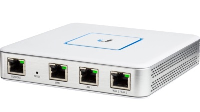
i. 1 x UniFi Security Gateway (USG); I deployed the USG which can handle 3Gbps bandwidth with advanced routing, stateful firewall, monitoring (deep packet inspection) and VPN. My NBN connection terminates here. It’s a fan-less device that I never had to reboot for non-performance in last 10 months. Price tag in Australia is $165 for the USG.

USG-PIC-JPEG-1

Details here – https://dl.ubnt.com/datasheets/unifi/UniFi_Security_Gateway_DS.pdf

ii. 1 x UniFi Cloud Key; its the PoE powered micro-computer running a Linux and apps that manages everything! This is also acting as the “Wireless LAN Controller (WLC!)”.  Price tag in Australia is $115.

UniFi-CloudKey-02

Details here – https://dl.ubnt.com/datasheets/unifi/UniFi_Cloud_Key_DS.pdf

iii. the last one is UniFi Access Points – this could be the AC series or the HD series or mix and match; there is NO number limit of “how many” APs can be managed by a single Cloud Key. Hope your doesn’t need support for 1000+ clients!! thats the limit.

You can have 1 x AP at each floor or 1 x east side and 1 x west side; even a single AP is also good enough to cover moderate big house with two floors. Price tag in Australia for the UAP-AC-PRO model (AC1750 each AP with 3×3 MIMO and dual band, PoE powered) is around $200 per AP. You can put them on the top any table or top of any shelve or showcase – it’s an excellent looking kit with blue LED circle light turned on.

UniFi-UAP-AC-PRO-01

Details here – https://www.ubnt.com/unifi/unifi-ap-ac-pro/

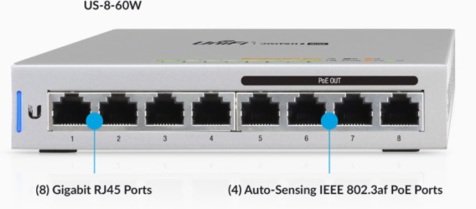
iv. 1 x UniFi PoE switch; UniFi switches are amazing fully managed layer 2 gigabit ethernet switch! you can see what is happening per ports, can do VLANs, trunks, jumbo frames, STP! I use the 8-ports PoE model. Price tag in Australia for US-8-60W-AU is $170. You can have the 24-port model if you need higher port density.

UniFi-8Port-PoE-01

Details here – https://www.ubnt.com/unifi-switching/unifi-switch-8/

Total solution cost with a single AP solution is AUD $650 (165+115+200+170) with 2 x APs is AUD $850.

Apart from the above devices you can add CCTV cameras and VoIP telephones to the same solution with centralised control.

Here are few key features that impressed me about the UniFi solution –

i. Fully compatible with Australian NBN; I tested connectivity with TPG and Optus; my friends are using with Aussie Broadband and IINET.
ii. Centralised fully cloud based management portal, excellent user interface, excellent Andriod and iPhone App!
iii. No subscription fees for the Cloud App or Mobile App.
iv. Loaded a lots of enterprise security features such as management frame protection, advanced encryptions etc; also Ubiquiti constantly releasing firmware updates and patches to keep up with latest security threats
v. Deep packet inspection, traffic monitoring, client monitoring, ports statistics – you can see what is happening and who is doing what!
vi. Wireless site survey
vii. Built-in DDNS & DNS-O-Matic support
viii. Plug-n-Play AP addition to the network anytime
ix. Single SSID across the whole wireless network and seamless wireless client handoff from one AP to another AP
x. L2TP/IPSec VPN support
xi. Guest access points & wireless access portal for guests
xii. Block/Unblock a client device using a single tap; good for parenting!
xiii. Easy single tap firmware upgrade through Mobile App or Cloud App/Portal
xiv. Single tap wireless speed testing built-in
xv. Ready for IoT integration

Here are few screenshots –

UniFi-Ctlr-01-JPEG

UniFi-Ctlr-02-JPEG

UniFi-Ctlr-3-JPEG

[following is from UniFi mobile app]

Unifi-MobileApp-JPEG

F5 iRule with Data Group

I often implement large list of IP and URL whitelisting/HTTP header based controls on F5 using iRules and Data Groups. What I found is “Data Groups” are one of the easiest way to handle a large number of matching keys and values!  As per F5 official documents – data group is the simplest way to maintain a list of permanently matched keys and values. A large list IP address or URL or any string/integer matching can be easily fit within iRule using data groups. Add/Remove entries within data groups are super easy.

Some old documents mentioned that data groups have impact on performance – truth is since TMOS v10.x and above data groups have minimum performance impact. F5 did some testing on performance using data groups and here’s some of the results (copied from F5 site):

The testing was done using 10,000 CPS, 1 HTTP request per TCP connection.

Baseline: TCP + HTTP profile + Blank iRule (when RULE_INIT { } )

Baseline results: Total CPU % used = 23%; TMM CPU % used = 16%; TMM Mem (MB) = 254

Check using iRule that I used in the video against datagroup with 1,000 entries (and no match found, so the entire group is forced to be searched).

Results: Total CPU % used = 25%; TMM CPU % used = 18%; TMM Mem (MB) = 259

Check against datagroup with 2,000 entries (no match found).

Results: Total CPU % used = 25%; TMM CPU % used = 18%; TMM Mem (MB) = 261

Check against datagroup with 10,000 entries (no match found).

Results: Total CPU % used = 26%; TMM CPU % used = 18%; TMM Mem (MB) = 277

So, even with a datagroup with 10,000 entries, the performance hit is minimal.

Here is an example of how to use data groups within iRules; lets say – to whitelist a list of IP address and block requests at TCP layer (TCP three-way handshake which happens before HTTP) – (i)we will create two test data groups and (ii)then bundle them together in an iRule and (iii)finally apply to a virtual server.

i. create data group A – iRules > Data Group List – create “test_data_group_A”; set type Address; enter all the IP address or you can import list file or add them to “/config/bigip.conf” (reload configuration if you edit the /config/bigip.conf manually). This is what it looks like –

ltm data-group internal /Common/test_data_group_A {
 records {
 1.1.1.1/32 { }
 1.1.1.2/32 { }
 1.1.1.3/32 { }
 2.2.2.1/32 { }
 2.2.2.22/32 { }
 }
 type ip
}

ii. follow the same above and create “test_data_group_B”
iii. create an iRule and put them together to allow requests only from the listed IPs (use “class match” command to refer to a data group) –

when CLIENT_ACCEPTED {
if {[class match [IP::client_addr] equals test_data_group_IP_A] } 
{}
elseif {[class match [IP::client_addr] equals test_data_group_IP_B] }
{} 
else
{drop }
}

iv. Apply the above iRule to a virtual server

Thats all! the above should only allow the IPs listed on the Data Groups.

In case if it is required to add/remove new IPs – then only add them to the data groups; no need to touch the iRule anymore.