This is the Part 2; Part 1 is here
Example configuration in here are based on Cisco Nexus 9K.
Configurations are very straight forward and simple. As I said earlier – if you have ever configured MP-BGP address families, this will be super easy for you. This doco describes L2 VNI only – there will be another one doco covering L3VNI.
L2 VNI is Type-2 route within EVPN VXLAN – which is “MAC with IP advertisement route”.
L3 VNI is Type-5 route within EVPN VXLAN – which is “IP prefix Route”.
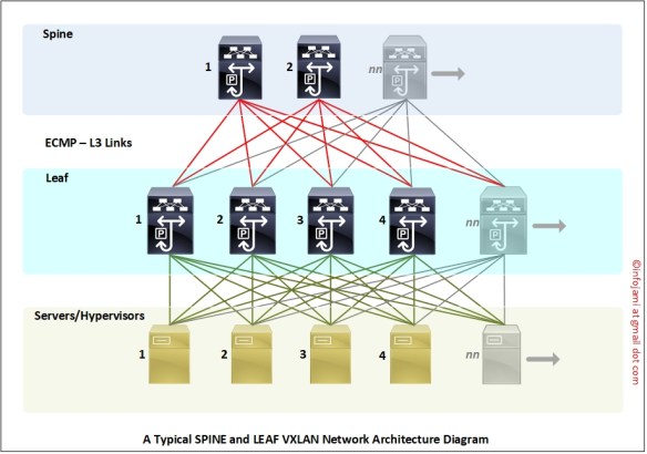
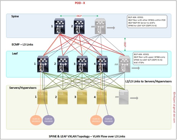
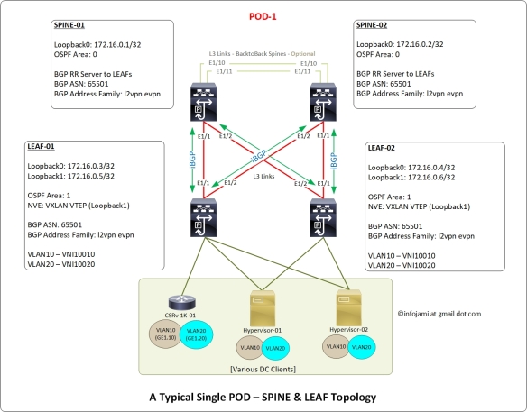
Following is the network topology design diagram I used here in this reference doco.
Notes regarding the network topology-
- 2 x SPINE switches (IP 172.16.0.1 and 172.16.0.2)
- 2 x LEAF switches (IP 172.16.0.3 and 172.16.0.4)
- IP address “unnumbered” configured on the interfaces connected between SPINE and LEAF
- 2 x VXLAN NVE VTEP interfaces on LEAF switches (source IP 172.16.0.5 and 172.16.0.6)
- SPINE switches are on the OSPF Area 0
- LEAF switches are on the OSPF Area 1
- iBGP peering between “SPINE to LEAF” – mesh iBGP peering topology
- Both SPINE switches are “route reflector” to the LEAF switches
- Physical layer connectivity are – “SPINE to LEAF” only. NO “LEAF to LEAF” or “SPINE to SPINE” required. However, “SPINE to SPINE” are optional on a single-pod which can be leverage later on a multi-pod or multi-site EVPN design.
- VNI ID for this POD-1 is 1xxxx; VNI ID for POD-2 will be 2xxxx. VNI IDs will be mapped to VLAN IDs. Example – VLAN ID 10 mapped to VNI 10010, VLAN ID 20 mapped to 10020.
- “route-distinguisher (RD)” ID number for this POD-1 is 100; RD ID for POD-2 will be 200.
Before we move to the “step by step” configuration – enable the following features on the Cisco Nexus switches.
Features to be enabled on the SPINE switches –
!
nv overlay evpn
feature ospf
feature bgp
!
Features to be enabled on the LEAF switches –
!
nv overlay evpn
feature ospf
feature bgp
feature interface-vlan
feature vn-segment-vlan-based
feature nv overlay
!
Step 1: Setup Loopback IPs on all the SPINE and LEAF switches
We need “loopback 0” IP address for router ID both for OSPF and BGP. Also, we will be using this loopback IP address for SPINE-LEAF connections as “ip unnumbered” source IP address.
Note: you need to configure OSPF routing first.
SPINE switches-
!---SPINE-01
!
interface loopback 0
description “Underlay – Interfaces and Router ID”
ip address 172.16.0.1/32
ip router ospf VXLAN-UNDERLAY area 0.0.0.0
!
!

!---SPINE-02
!
interface loopback 0
description “Underlay – Interfaces and Router ID”
ip address 172.16.0.2/32
ip router ospf VXLAN-UNDERLAY area 0.0.0.0
!
LEAF switches-
!---LEAF-01
!
interface loopback 0
description “Underlay – Interfaces and Router ID”
ip address 172.16.0.3/32
ip router ospf VXLAN-UNDERLAY area 1.1.1.1
!
!

!---LEAF-02
!
interface loopback 0
description “Underlay – Interfaces and Router ID”
ip address 172.16.0.4/32
ip router ospf VXLAN-UNDERLAY area 1.1.1.1
!
Step 2: Setup OSPF routing and Ethernet interfaces IP address
SPINE-LEAF VXLAN is a “full mesh” network – thus, it is hard to track interface IP addresses if they are configured individually with unique IP address; it will be too many IPs and too many IP Subnets!! IP address “unnumbered” is a nice way to avoid too many IPs and Subnets.
I will be using the same “loopback 0” IP address to all the interconnect interfaces between SPINE & LEAF switches with “ip unnumbered” feature.
Interfaces E1/1 & E1/2 are connected to each other between SPINE and LEAF; SPINE to SPINE connection using interfaces E1/10 & E1/11 on both the switches (as per the above network design diagram).
!---SPINE-01 and SPINE-02
!
interface e1/1,e1/2
no switchport
description “connected to LEAF switches – IP Fabric”
mtu 9216
medium p2p
ip unnumbered loopback0
ip ospf authentication message-digest
ip ospf message-digest-key 0 md5 3 yourOSPFsecret
ip ospf network point-to-point
no ip ospf passive-interface
ip router ospf VXLAN-UNDERLAY area 1.1.1.1
no shutdown
!
!---LEAF-01 and LEAF-02
!
interface e1/1,e1/2
no switchport
description “connected to SPINE switches – IP Fabric”
mtu 9216
medium p2p
ip unnumbered loopback0
ip ospf authentication message-digest
ip ospf message-digest-key 0 md5 3 yourOSPFsecret
ip ospf network point-to-point
no ip ospf passive-interface
ip router ospf VXLAN-UNDERLAY area 1.1.1.1
no shutdown
!
!---SPINE-01 and SPINE-02
!---This is NOT required on a single-POD only solution
!
interface e1/10,e1/11
no switchport
description “connected to SPINE switches – back-to-back IP Fabric”
mtu 9216
medium p2p
ip unnumbered loopback0
ip ospf authentication message-digest
ip ospf message-digest-key 0 md5 3 yourOSPFsecret
ip ospf network point-to-point
no ip ospf passive-interface
ip router ospf VXLAN-UNDERLAY area 0.0.0.0
no shutdown
!
!---all the SPINE & LEAF; adjust the loopback0 IP address for each sw
!
router ospf VXLAN-UNDERLAY
router-id 172.16.0.LOOPBACK0-IP
passive-interface default
!
At this stage – OSPF adjacency should be formed between SPINE and LEAF and SPINE to SPINE switches.
Verify your OSPF configuration and connectivity between switches-
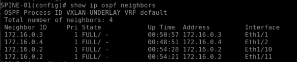
show ip ospf neighbors
show ip ospf route
show ip ospf database
show ip ospf interface
Make sure you able to ping between all the SPINE and LEAF switches.
(Screenshot – “show ip ospf neighbor” from SPINE-01)
Step 3: Setup MP-BGP peering across all the SPINE and LEAF switches
I will now configure MP-BGP along with address family “l2vpn evpn” on all the switches; we will have to enable “send-community extended” on all the BGP peer to allow exchange of L2/L3 evpn VXLAN encapsulations.
- iBGP peering between SPINE-01 and SPINE-02;
- iBGP peering from all SPINE to LEAF – SPINE switches are route reflector server to LEAF switches
- NO LEAF to LEAF BGP peering
!
!---SPINE switches MP-BGP config SPINE-01
!---adjust the RID IP address for SPINE-02
!---iBGP to LEAF switches
!
router bgp 65501
  router-id 172.16.0.1
  log-neighbor-changes
  address-family l2vpn evpn
    retain route-target all
  !
  neighbor 172.16.0.3
    remote-as 65501
    description "LEAF-01 - iBGP peer - RR client"
    password 3 ef6a8875f8447eac
    update-source loopback0
    address-family l2vpn evpn
      send-community extended
      route-reflector-client
  !
  neighbor 172.16.0.4
    remote-as 65501
    description "LEAF-02 - iBGP peer - RR client"
    password 3 ef6a8875f8447eac
    update-source loopback0
    address-family l2vpn evpn
      send-community extended
      route-reflector-client
!
!---LEAF switche LEAF-01
!---adjust the RID IP address for LEAF-02
!---iBGP peering to SPINEs in the same POD only
!
router bgp 65501
  router-id 172.16.0.3
  address-family l2vpn evpn
    retain route-target all
  !
  neighbor 172.16.0.1
    remote-as 65501
    description "SPINE-01 - iBGP peer - RR server"
    password 3 ef6a8875f8447eac
    update-source loopback0
    address-family l2vpn evpn
      send-community extended
  !
  neighbor 172.16.0.2
    remote-as 65501
    description "SPINE-02 - iBGP peer - RR server"
    password 3 ef6a8875f8447eac
    update-source loopback0
    address-family l2vpn evpn
      send-community extended
!
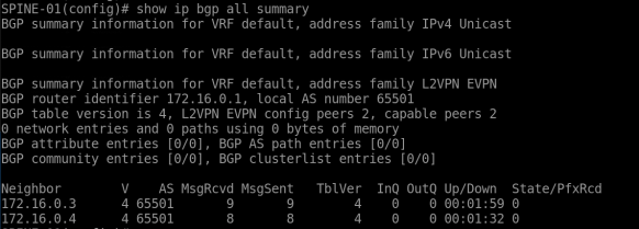
BGP Verification –
show bgp all summary
show bgp all neighbors 172.16.0.1
show bgp all neighbors 172.16.0.2
show bgp all neighbors 172.16.0.3
show bgp all neighbors 172.16.0.4
Make sure BGP peering status is “Established” for all.
(Screenshot – “show bgp all summary” from SPINE-01)
As of now – all the above configurations are typical routing & interface configurations. Next sections describe VTEP, NVE, VNI & EVPN configurations.
Step 4: Setup NVE interface on the LEAF switches only
NVE interface is the VXLAN VTEP. This only requires to configured on the LEAF switches. VXLAN encapsulation happen on the NVE interfaces.
The VXLAN encapsulation/decapsulation concept is very similar to MPLS “PE” and “P” routers; source “PE” routers encapsulate MPLS labels and transport them over the “P” routers to the destination “PE” routers. Source LEAF switch NVE VTEP interface encapsulate VXLAN packets and transport them over SPINE switches to destination LEAF switch NVE VTEP interface.
NVE interface requires a dedicated loopback interface; we will setup “loopback 1” on both the LEAF and bind them to “NVE 1” interface.
!---LEAF-01
!
interface loopback 1
description “Underlay – NVE VTEP source IP”
ip address 172.16.0.5/32
ip router ospf VXLAN-UNDERLAY area 1.1.1.1
!

!---LEAF-02
!
interface loopback 1
description “Underlay – NVE VTEP source IP”
ip address 172.16.0.6/32
ip router ospf VXLAN-UNDERLAY area 1.1.1.1
!

!---both LEAF-01 and LEAF-02
!
interface nve1
  no shutdown
  description "VXLAN - VTEP interface"
  host-reachability protocol bgp
  source-interface loopback1
!
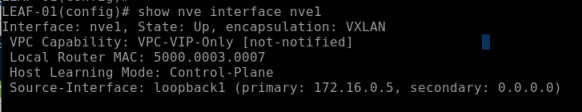
Verification –
>ping loopback1 IP address between LEAF-01 and LEAF-02; make sure they are reachable
show interface nve1; make sure nve1 interface is UP
Step 5: Create VLAN, VNI and configure EVPN
We will create traditional VLAN IDs and name, then associate an unique VNI ID to the VLAN ID; finally, we will configure the VNI ID onto NVE and EVPN.
!---on both the LEAF-01 and LEAF-02
!
vlan 10
name VLAN10-TEST
vn-segment 10010
!
vlan 20
name VLAN20-TEST
vn-segment 10020
!
Now add the above VLAN10 and VLAN20 onto NVE1 and EVPN on both the switches-
!---on both the LEAF-01 and LEAF-02
!
interface nve1
!
member vni 10010
    ingress-replication protocol bgp
  member vni 10020
    ingress-replication protocol bgp
!

!---both the LEAF-01 and LEAF-02
!
evpn
  !
  vni 10010 l2
    rd auto
    route-target import 100:10010
    route-target export 100:10010
  !
  vni 10020 l2
    rd auto
    route-target import 100:10020
    route-target export 100:10020
!
At this stage MP-BGP EVPN start exchange VXLAN encap packets between NVE VTEP peer LEAF switches.
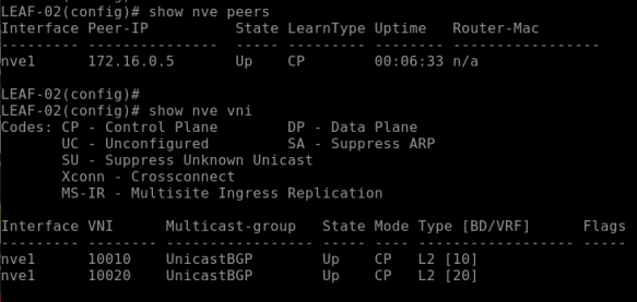
Verification –
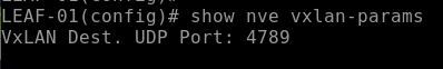
show nve peers; make sure its showing remote IP of peer & status is UP
show nve vni; make sure status is UP

show nve interface nve1
show nve vxlan-params
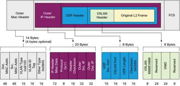
Following screenshot showing NVE port number on Cisco Nexus UDP/4789 –
Part 6: Verification – MAC Learning, VLAN, VNI ID, VXLAN, BGP EVPN
This is the final part.
As a part of end-to-end L2 VNI VLAN test & verification – we have configured the interface “E1/15” on both the LEAF switches as a “trunk” and connected two routers and configured VLAN10 on them.
Router-01 interface MAC address is “50:00:00:05:00:00”; this is connected to LEAF-01; this MAC is local to LEAF-01; IP address configured here is 192.168.10.1/24.
Router-01 interface MAC address is “50:00:00:06:00:00”; this is connected to LEAF-02; this MAC is local to LEAF-02; IP address configured here is 192.168.10.2/24.
Let’s verify MAC address learning on LEAF-01 and LEAF-02 for VLAN10 –
>ping 192.168.10.2 from Router-01; same way ping 192.168.10.1 from Router-02
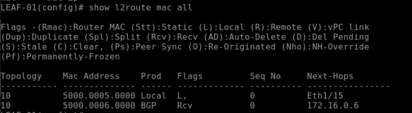
show l2route mac all
show mac address-table (on the NXOS 9000v this command is >show system internal l2fwder mac)
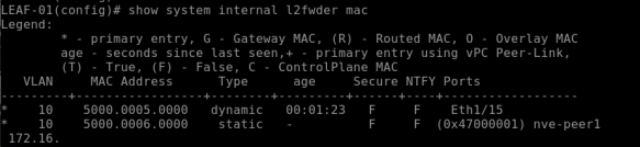
The above command on the LEAF-01 returns the following output –
This shows the local MAC “50:00:00:05:00:00” as “Local” on “Port E1/15”
This will show the remote MAC “50:00:00:06:00:00” as “BGP” learned and port is “nve-peer1”
The above command on the LEAF-02 will return the following output –
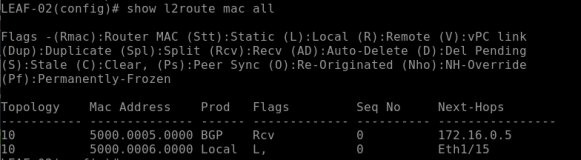
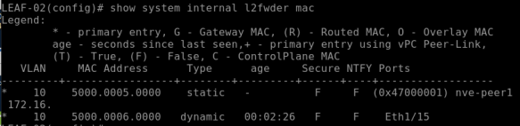
This shows the local MAC “50:00:00:06:00:00” as “Local“ and “Port E1/15”
This will show the remote MAC “50:00:00:05:00:00” as “BGP” learned and port is “nve-peer1”
The folloiwng BGP l2vpn command will show EVPN MAC, VNI ID & Route-Type
show bgp l2vpn evpn vni-id 10010
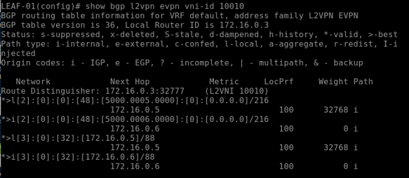
This above command returns BGP EVPN details for the VNI 10010 (VLAN 10); note the first part *>l[2]” – this specify the type of route which is Type-2 for L2VNI.
The above verificaiton clearly showing remote “Layer 2 MAC address” learning over BGP which is MAC over Layer 3 routing protocol!!
Thats all.