My BGP Notes – Part 2

This is part 2 of “My BGP Notes” series; the part 1 link is here My BGP Notes – Part 1

Part 2 is also my notes on BGP fundamentals; this covers “BGP Neighbor States” and “BGP AFI, SAFI”.

Part 2.1 – BGP Neighbor States

BGP uses the Finite State Machine (FSM) to maintain a table of all BGP peers and their operational status; the FSM model defines – “what actions” should be taken by the BGP engine and “when” in the simplest manner.
 
BGP sessions are peer-to-peer sessions between neighbors; BGP neighbor states are the followings:
 
i. Idle
ii. Connect
iii. Active
iv. OpenSent
v. OpenConfirm
vi. Established

“Idle” State
 
->This is the first stage of the BGP FSM; the Idle state occurs when someone configures a new BGP neighbor or resets an “Established” peer session.
->In this state, BGP detects a start event, listens for a new connection (TCP/179) from a peer, and initiates a TCP connection to remote peer.
->When successful, BGP moves onto the next state “Connect” state.
->If an error causes BGP to go back to the “Idle” state for a second time, the “ConnectRetryTimer” is set to 60 seconds and must decrement to zero before the connection is initiated again. Further failures leave the “Idle state” result in the “ConnectRetryTimer” doubling in length from the previous time.

“Connect” State
 
->In this state, BGP waits for the 3-way TCP handshake to complete successfully.
->Upon a successful TCP connection, BGP sends an “OPEN” message to peer and moves onto next “OpenSent” state.
->If the above TCP connection fails, then BGP goes next to “Active” state and resets the “ConnectRetryTimer” timer.
->If any other input is received, BGP goes back to “Idle” state.
 
During this stage, the neighbor with the “higher IP address” manages the connection. The router initiating the request uses a dynamic source port, but the destination port is always TCP/179.

“Active” State
 
->In this state, BGP speaker tries to connect to peer by initiating “another” new TCP 3-way handshake.
->If a TCP connection is established, an “OPEN” message is sent, the Hold Timer is set to 4 minutes (on Cisco), and the state moves to next “OpenSent” state.
->If this attempt for TCP connection fails, the state moves back to the “Connect” state and resets the “ConnectRetryTimer”.
->If any other input is received, BGP goes back to “Idle” state.

“OpenSent” State
 
->In this state, an “OPEN” message has been sent from the originating router and is awaiting an “OPEN” message from the peer. After the originating router receives the “OPEN” message from the peer, both “OPEN” messages are checked and compared for errors.
->The items are being compared “what is configured” on the peers are: BGP Versions/RID/ASN/Security Params/TTL/SourceIP/and similar params.
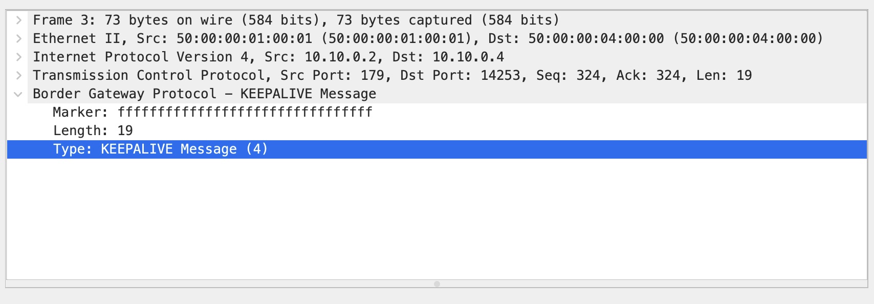
->Upon successful “OPEN” messages exchange, BGP sets the Hold Time (using the lower value) and a “KEEPALIVE” message is sent; BGP then goes onto next “OpenConfirm” state.
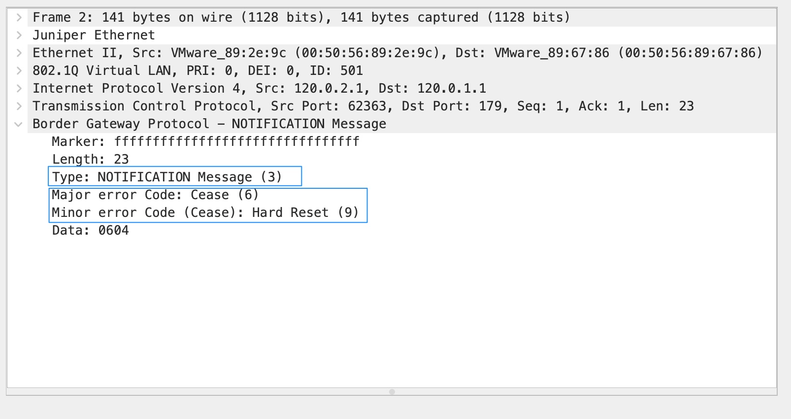
->If an error is found in the “OPEN” message, BGP sends a “NOTIFICATION” message and the state is moved back to “Idle” state.
->If TCP receives a disconnect message, BGP closes the connection, resets the “ConnectRetryTimer”, and sets the state back to “Active”.
->If any other input is received, BGP goes back to “Idle” state.

“OpenConfirm” State
 
->In this state, BGP waits for a “KEEPALIVE” message or “NOTIFICATION” message from peer.  
->Upon successful receipt of a peer’s “KEEPALIVE” message, the state moves next to “Established” state.
->If the hold timer expires, a stop event occurs, or a “NOTIFICATION” message is received, then the state is moved back to “Idle” state.

“Established” State

->In this state, the BGP session is established.
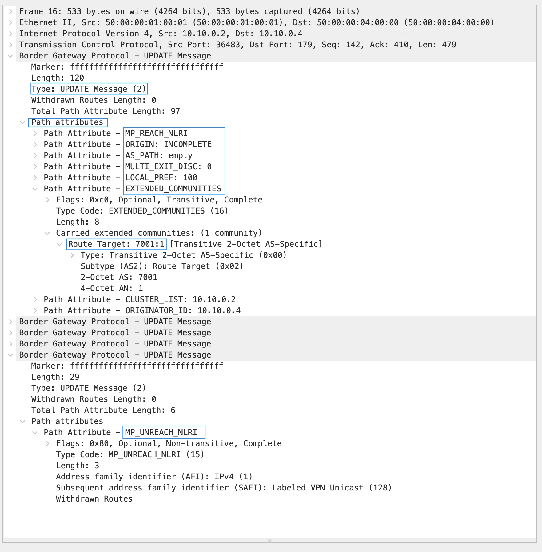
->BGP neighbors exchange routes via “UPDATE” messages.
->As “UPDATE” and “KEEPALIVE” messages are received, the Hold Timer is reset.
->If the Hold Timer expires or an error is detected (a “NOTIFICATION” message), BGP moves the neighbor state back to the “Idle” state.

In summary; if no error, then BGP neighbor state progressions are the followings:

Idle -> Connect -> OpenSent -> OpenConfirm -> Established.
 
If there any error occurs, then BGP neighbor state progressions “could be” the followings:

Idle -> Connect (back to “Idle”) -> Active (back to “Connect” or “Idle”) -> OpenSent (back to “Active” or “Idle”) -> OpenConfirm (back to “Idle”) -> Established (back to “Idle”).

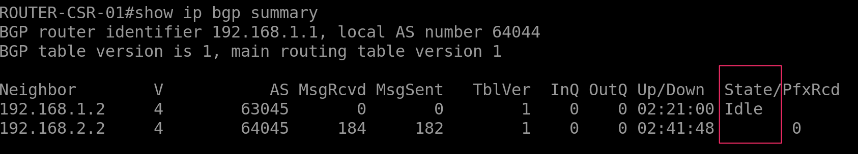
The following screenshot is taken on a Cisco CSRv router – BGP “Idle” state:

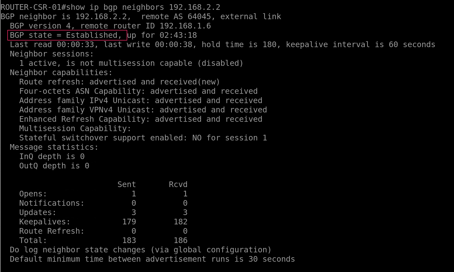
The following screenshot is taken on a Cisco CSRv router – BGP “Established” state:

Part 2.2 – BGP AFI and SAFI

AFI means “Address Family Indicator”
SAFI means “Subsequent Address Family Indicator”.

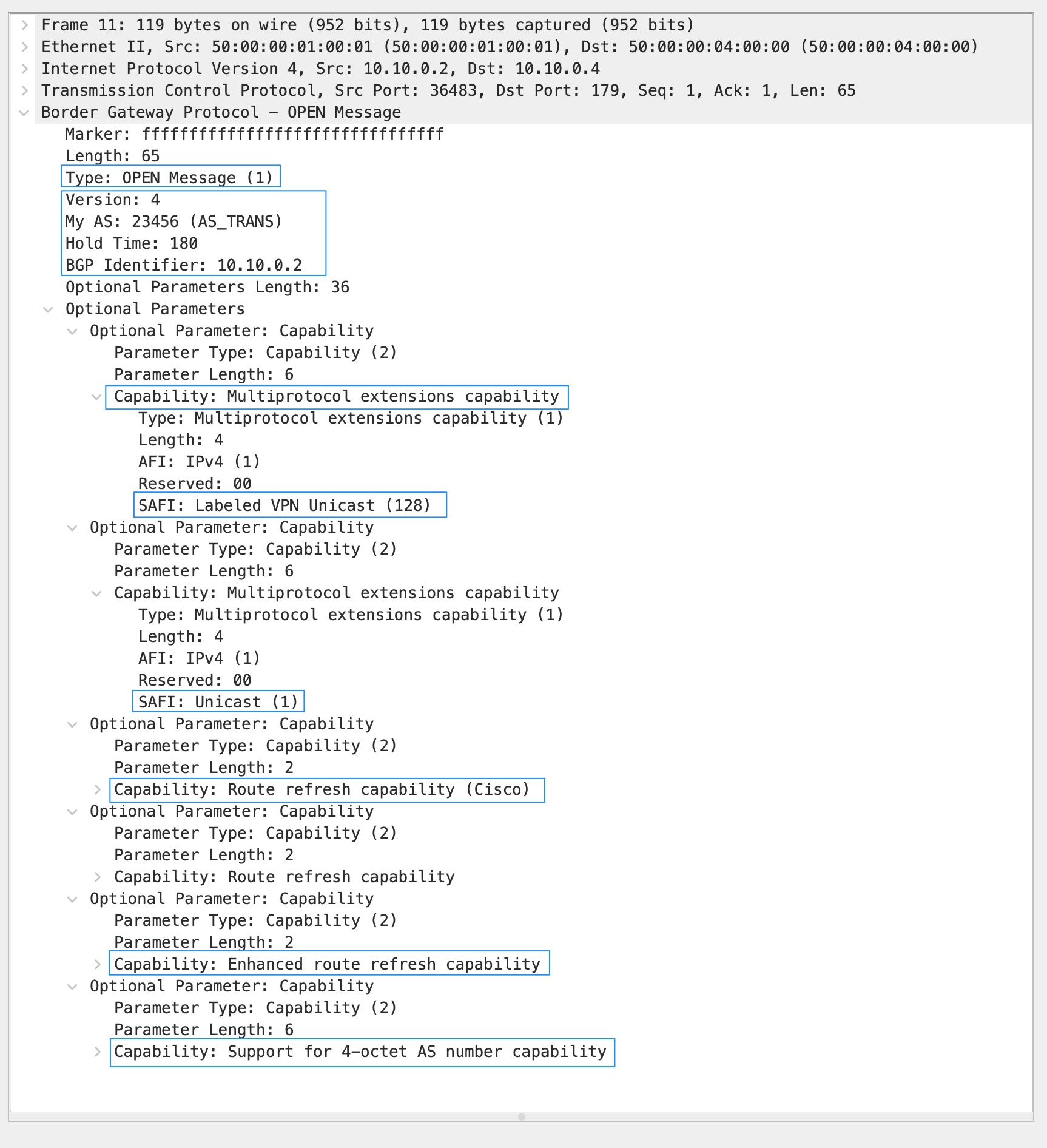
They are used in the “Multiprotocol Extensions” to BGP (MP-BGP) and are exchanged during neighbor capability exchange (in the BGP “OPEN” message) during the process of establishing the peers. They basically tell the remote peer what address families (IPv4, IPv6, VPNv4, VPNv6…) and what specific sub-address family (multicast, unicast, vrf, evpn, vpls, flow-spec…) the local BGP router will transport the routes for.

AFI is 16-bit.
SAFI is 8-bit.

A few well-known AFI-SAFI are the followings:

1-1 is for IPv4 (AFI:1) unicast forwarding (SAFI:1)
1-2 is for IPv4 (AFI:1) multicast forwarding (SAFI:2)
1-128 is for IPv4 (AFI:1) VPNv4 (MPLS-labeled VPN address SAFI:128)
1-132 is for IPv4 (AFI:1) VRF – Route Target constrains (SAFI:132)
1-133 is for IPv4 (AFI:1) Flow-spec (SAFI:133)

2-1 is for IPv6 (AFI:2) unicast forwarding (SAFI:1)
2-2 is for IPv6 (AFI:2) multicast forwarding (SAFI:1)
2-128 is for IPv6 (AFI:2) VPNv6 (MPLS-labeled VPN address SAFI:128)

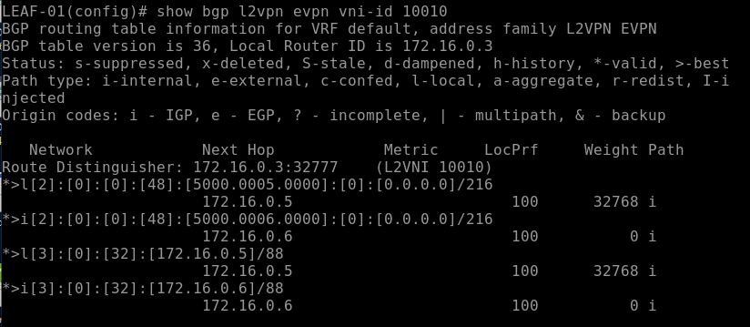
25-70 is for L2VPN (AFI:25) EVPN (SAFI:70)

AFI: 0 is reserved
AFI: 32-16383 are unassigned
AFI: 16400-65534 are unassigned

In the future, there will be many new AFI and SAFI adopted in MP-BGP as new capabilities!

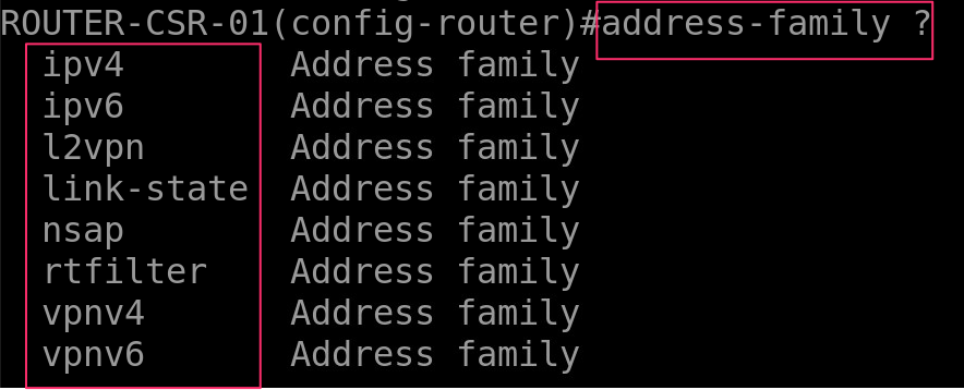
The following screenshot is taken on a Cisco CSRv router – showing available AFIs:

The following screenshot is taken on a Cisco CSRv router – showing available SAFIs within IPv4:

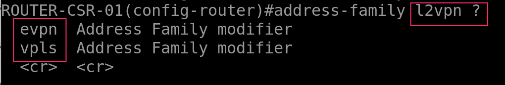
The following screenshot is taken on a Cisco CSRv router – showing available SAFIs within L2VPN:

MP-BGP AFI and SAFI References:
https://www.iana.org/assignments/address-family-numbers/address-family-numbers.xhtml
https://www.iana.org/assignments/safi-namespace/safi-namespace.xhtml

My BGP Notes – Part 1

My BGP notes. It’s going to be a series of posts here….My BGP Notes 1,2,3,……

(Part 2 is here My BGP Notes – Part 2)

I have been keeping BGP notes on many scattered places. A lot of times when I want to refresh my BGP knowledge – I could not find the notes I kept earlier easily and end up Googling (yes, BGP references are everywhere but I prefer my own way of taking notes). Hence, I am adding my BGP notes on my blog page.

To me, BGP is not only a routing protocol but rather BGP is a big “network application” I use in designing networks in enterprise connectivity, data centre networking, and ISP connectivities.

This is “part 1” of my notes; I will start with the fundamentals of BGP.

The Basics

-RFC 1654 defines BGP as an EGP “path-vector” routing protocol.
-BGP is designed for IPv4. (But Multiprotocol BGP – MP-BGP works with IPv6).
-BGP configuration requires Autonomous System Numbers (ASN).
-ASN numbering was originally 16-bits long number (2-bytes); 1-65,535.
-Extended ASN ranges are 32-bit (4-bytes) number up to 4,294,967,294.
-ASN 64,512–65,535 are private within the 2-bytes range.
-ASN 4,200,000,000–4,294,967,294 are private within the 4-bytes range.
-The BGP version we use is BGP v4.
-BGP loop prevention is based on the path-vector mechanism.
-BGP adds its own AS number (AS_PATH) to the prefixes it announces to peers and discards messages if its own AS number is found in a received message.
-BGP advertises routes learned from an eBGP peer to all BGP peers, including both eBGP and iBGP peers.
-BGP advertises routes learned from an iBGP peer to eBGP peers, and not to another iBGP peer. Routes advertisements across iBGP peers can be achieved with the help of a Route-Reflector server.
-Multiprotocol BGP (MP-BGP) supports a wide range of address families besides IPv4 (l2vpn, l3vpn, evpn, unicast, multicast, flow-spec…).

BGP Sessions

-A BGP session refers to the established adjacency between two BGP speaker routers. BGP sessions are always point-to-point between two BGP speakers.
-A BGP session can be iBGP, when a BGP session is established within the same ASN number; both BGP speakers belong to the same ASN.
-A BGP session can be eBGP, when BGP speakers belong to different ASN numbers.
-iBGP administrative distance is 200 whereas eBGP administrative distance is 20.
-BGP speakers do not use Hello packets to discover neighbors like IGP routing protocols.
-A BGP session can not be discovered automatically like OSPF/EIGRP/RIP.
-BGP uses TCP port 179 to communicate with neighbors.
-A BGP session starts with a TCP 3-way handshake.

BGP Messages

BGP speakers use four (04) messages to communicate between themselves.

(01)OPEN message
(02)KEEPALIVE message
(03)UPDATE message
(04)NOTIFICATION message

Some vendor implementations use a fifth message – this is called “Route Refresh” message; however, this is found in the OPEN message for Cisco routers (part of optional capabilities).

BGP messages are easy to identify in captured packets using Wireshark. Let’s see what we found in different BGP messages.

OPEN Message

After the 3-way TCP handshake, the very first BGP message is called “Open”. Both BGP speakers negotiate session capabilities before a BGP peering is established.

Screenshot of OPEN message following.

Based on the OPEN message captured, we found the following items here –

-BGP version
-ASN number
-Hold Time
-BGP identifier (RID)
-BGP capabilities (Multiprotocol extensions, Route refresh capabilities, Graceful Restart capabilities, support for Extended ASN 4-bytes octet)

Notes on Hold Time: BGP default hold time suggested is 90 seconds (3x of keepalive) and keepalives is 30 seconds. BGP default keepalive and hold time are vendor specific these days.

KEEPALIVE Message

Although BGP uses TCP 3-way handshake, it does not rely on TCP connection states (ack mechanism) to check if the peer is still alive.

BGP KEEPALIVE is a simple message format sent every 1/3 of configured Hold Time interval. BGP configuration with 90 seconds Hold Time will send KEEPALIVE every 30 seconds. If Hold Time is set to zero seconds – then there is no KEEPALIVE!

Screenshot of KEEPALIVE message following.

UPDATE Message

BGP network advertisements are included in UPDATE messages. BGP sends both feasible routes and withdrawn routes (previously advertised). Route prefixes and BGP Path Attributes (PA) are found in BGP NLRI. MP_REACH_NLRI and MP_UNREACH_NLRI along with AFI and SAFI details are found in UPDATE messages.

An UPDATE message can act as KEEPALIVE to reduce noise in BGP communications.

Screenshot of the UPDATE message following.

NOTIFICATION Message

NOTIFICATION message is sent if there is an error found in BGP communication between BGP speakers. Notification codes include “Cease”, “Hard Reset” etc.

Screenshot of NOTIFICATION message following.

BGP Message Header

BGP messages header has the following three items –

(01)Marker; this is filled with all fffffffff……16-octets for all message types.
(02)Length; length can be different for different types of message and also based on what information are in the message. The total length is mentioned on the top of the header; breakdowns are in each path attributes section. Min length size is 19 bytes and the max size is 4096 bytes.
(03)Type; Open/Update/Keepalive/Notificaiton.

VXLAN, MBGP EVPN with ingress replication – Part 2 – Configure VXLAN L2 VNI on a single POD

This is the Part 2; Part 1 is here

Example configuration in here are based on Cisco Nexus 9K.

Configurations are very straight forward and simple. As I said earlier – if you have ever configured MP-BGP address families, this will be super easy for you. This doco describes L2 VNI only – there will be another one doco covering L3VNI.

L2 VNI is Type-2 route within EVPN VXLAN – which is “MAC with IP advertisement route”.

L3 VNI is Type-5 route within EVPN VXLAN – which is “IP prefix Route”.

Following is the network topology design diagram I used here in this reference doco.

Notes regarding the network topology-

  • 2 x SPINE switches (IP 172.16.0.1 and 172.16.0.2)
  • 2 x LEAF switches (IP 172.16.0.3 and 172.16.0.4)
  • IP address “unnumbered” configured on the interfaces connected between SPINE and LEAF
  • 2 x VXLAN NVE VTEP interfaces on LEAF switches (source IP 172.16.0.5 and 172.16.0.6)
  • SPINE switches are on the OSPF Area 0
  • LEAF switches are on the OSPF Area 1
  • iBGP peering between “SPINE to LEAF” – mesh iBGP peering topology
  • Both SPINE switches are “route reflector” to the LEAF switches
  • Physical layer connectivity are – “SPINE to LEAF” only. NO “LEAF to LEAF” or “SPINE to SPINE” required. However, “SPINE to SPINE” are optional on a single-pod which can be leverage later on a multi-pod or multi-site EVPN design.
  • VNI ID for this POD-1 is 1xxxx; VNI ID for POD-2 will be 2xxxx. VNI IDs will be mapped to VLAN IDs. Example – VLAN ID 10 mapped to VNI 10010, VLAN ID 20 mapped to 10020.
  • “route-distinguisher (RD)” ID number for this POD-1 is 100; RD ID for POD-2 will be 200.

POD-Underlay-Overlay-SinglePOD-Diag1.2

Before we move to the “step by step” configuration – enable the following features on the Cisco Nexus switches.

Features to be enabled on the SPINE switches –

!
nv overlay evpn
feature ospf
feature bgp
!

Features to be enabled on the LEAF switches –

!
nv overlay evpn
feature ospf
feature bgp
feature interface-vlan
feature vn-segment-vlan-based
feature nv overlay
!

Step 1: Setup Loopback IPs on all the SPINE and LEAF switches

We need “loopback 0” IP address for router ID both for OSPF and BGP. Also, we will be using this loopback IP address for SPINE-LEAF connections as “ip unnumbered” source IP address.

Note: you need to configure OSPF routing first.

SPINE switches-

!---SPINE-01
!
interface loopback 0
description “Underlay – Interfaces and Router ID”
ip address 172.16.0.1/32
ip router ospf VXLAN-UNDERLAY area 0.0.0.0
!
!

!---SPINE-02
!
interface loopback 0
description “Underlay – Interfaces and Router ID”
ip address 172.16.0.2/32
ip router ospf VXLAN-UNDERLAY area 0.0.0.0
!

LEAF switches-

!---LEAF-01
!
interface loopback 0
description “Underlay – Interfaces and Router ID”
ip address 172.16.0.3/32
ip router ospf VXLAN-UNDERLAY area 1.1.1.1
!
!

!---LEAF-02
!
interface loopback 0
description “Underlay – Interfaces and Router ID”
ip address 172.16.0.4/32
ip router ospf VXLAN-UNDERLAY area 1.1.1.1
!

Step 2: Setup OSPF routing and Ethernet interfaces IP address

SPINE-LEAF VXLAN is a “full mesh” network – thus, it is hard to track interface IP addresses if they are configured individually with unique IP address; it will be too many IPs and too many IP Subnets!! IP address “unnumbered” is a nice way to avoid too many IPs and Subnets.

I will be using the same “loopback 0” IP address to all the interconnect interfaces between SPINE & LEAF switches with “ip unnumbered” feature.

Interfaces E1/1 & E1/2 are connected to each other between SPINE and LEAF; SPINE to SPINE connection using interfaces E1/10 & E1/11 on both the switches (as per the above network design diagram).

!---SPINE-01 and SPINE-02
!
interface e1/1,e1/2
no switchport
description “connected to LEAF switches – IP Fabric”
mtu 9216
medium p2p
ip unnumbered loopback0
ip ospf authentication message-digest
ip ospf message-digest-key 0 md5 3 yourOSPFsecret
ip ospf network point-to-point
no ip ospf passive-interface
ip router ospf VXLAN-UNDERLAY area 1.1.1.1
no shutdown
!
!---LEAF-01 and LEAF-02
!
interface e1/1,e1/2
no switchport
description “connected to SPINE switches – IP Fabric”
mtu 9216
medium p2p
ip unnumbered loopback0
ip ospf authentication message-digest
ip ospf message-digest-key 0 md5 3 yourOSPFsecret
ip ospf network point-to-point
no ip ospf passive-interface
ip router ospf VXLAN-UNDERLAY area 1.1.1.1
no shutdown
!
!---SPINE-01 and SPINE-02
!---This is NOT required on a single-POD only solution
!
interface e1/10,e1/11
no switchport
description “connected to SPINE switches – back-to-back IP Fabric”
mtu 9216
medium p2p
ip unnumbered loopback0
ip ospf authentication message-digest
ip ospf message-digest-key 0 md5 3 yourOSPFsecret
ip ospf network point-to-point
no ip ospf passive-interface
ip router ospf VXLAN-UNDERLAY area 0.0.0.0
no shutdown
!
!---all the SPINE & LEAF; adjust the loopback0 IP address for each sw
!
router ospf VXLAN-UNDERLAY
router-id 172.16.0.LOOPBACK0-IP
passive-interface default
!

At this stage – OSPF adjacency should be formed between SPINE and LEAF and SPINE to SPINE switches.

Verify your OSPF configuration and connectivity between switches-

show ip ospf neighbors
show ip ospf route
show ip ospf database
show ip ospf interface

Make sure you able to ping between all the SPINE and LEAF switches.

(Screenshot – “show ip ospf neighbor” from SPINE-01)

OSPF-Neighbors

Step 3: Setup MP-BGP peering across all the SPINE and LEAF switches

I will now configure MP-BGP along with address family “l2vpn evpn” on all the switches; we will have to enable “send-community extended” on all the BGP peer to allow exchange of L2/L3 evpn VXLAN encapsulations.

  • iBGP peering between SPINE-01 and SPINE-02;
  • iBGP peering from all SPINE to LEAF – SPINE switches are route reflector server to LEAF switches
  • NO LEAF to LEAF BGP peering
!
!---SPINE switches MP-BGP config SPINE-01
!---adjust the RID IP address for SPINE-02
!---iBGP to LEAF switches
!
router bgp 65501
  router-id 172.16.0.1
  log-neighbor-changes
  address-family l2vpn evpn
    retain route-target all
  !
  neighbor 172.16.0.3
    remote-as 65501
    description "LEAF-01 - iBGP peer - RR client"
    password 3 ef6a8875f8447eac
    update-source loopback0
    address-family l2vpn evpn
      send-community extended
      route-reflector-client
  !
  neighbor 172.16.0.4
    remote-as 65501
    description "LEAF-02 - iBGP peer - RR client"
    password 3 ef6a8875f8447eac
    update-source loopback0
    address-family l2vpn evpn
      send-community extended
      route-reflector-client
!
!---LEAF switche LEAF-01 
!---adjust the RID IP address for LEAF-02
!---iBGP peering to SPINEs in the same POD only
!
router bgp 65501
  router-id 172.16.0.3
  address-family l2vpn evpn
    retain route-target all
  !
  neighbor 172.16.0.1
    remote-as 65501
    description "SPINE-01 - iBGP peer - RR server"
    password 3 ef6a8875f8447eac
    update-source loopback0
    address-family l2vpn evpn
      send-community extended
  !
  neighbor 172.16.0.2
    remote-as 65501
    description "SPINE-02 - iBGP peer - RR server"
    password 3 ef6a8875f8447eac
    update-source loopback0
    address-family l2vpn evpn
      send-community extended
!

BGP Verification –

show bgp all summary
show bgp all neighbors 172.16.0.1
show bgp all neighbors 172.16.0.2
show bgp all neighbors 172.16.0.3
show bgp all neighbors 172.16.0.4

Make sure BGP peering status is “Established” for all.

(Screenshot – “show bgp all summary” from SPINE-01)

BGP-all-summary-1.1

As of now – all the above configurations are typical routing & interface configurations. Next sections describe VTEP, NVE, VNI & EVPN configurations.

Step 4: Setup NVE interface on the LEAF switches only

NVE interface is the VXLAN VTEP. This only requires to configured on the LEAF switches. VXLAN encapsulation happen on the NVE interfaces.

The VXLAN encapsulation/decapsulation concept is very similar to MPLS “PE” and “P” routers; source “PE” routers encapsulate MPLS labels and transport them over the “P” routers to the destination “PE” routers. Source LEAF switch NVE VTEP interface encapsulate VXLAN packets and transport them over SPINE switches to destination LEAF switch NVE VTEP interface.

NVE interface requires a dedicated loopback interface; we will setup “loopback 1” on both the LEAF and bind them to “NVE 1” interface.

!---LEAF-01
!
interface loopback 1
description “Underlay – NVE VTEP source IP”
ip address 172.16.0.5/32
ip router ospf VXLAN-UNDERLAY area 1.1.1.1
!

!---LEAF-02
!
interface loopback 1
description “Underlay – NVE VTEP source IP”
ip address 172.16.0.6/32
ip router ospf VXLAN-UNDERLAY area 1.1.1.1
!

!---both LEAF-01 and LEAF-02
!
interface nve1
  no shutdown
  description "VXLAN - VTEP interface"
  host-reachability protocol bgp
  source-interface loopback1
!

show-nve-interface

Verification –

>ping loopback1 IP address between LEAF-01 and LEAF-02; make sure they are reachable

show interface nve1; make sure nve1 interface is UP

Step 5: Create VLAN, VNI and configure EVPN

We will create traditional VLAN IDs and name, then associate an unique VNI ID to the VLAN ID; finally, we will configure the VNI ID onto NVE and EVPN.

!---on both the LEAF-01 and LEAF-02
!
vlan 10
name VLAN10-TEST
vn-segment 10010
!
vlan 20
name VLAN20-TEST
vn-segment 10020
!

Now add the above VLAN10 and VLAN20 onto NVE1 and EVPN on both the switches-

!---on both the LEAF-01 and LEAF-02
!
interface nve1
!
member vni 10010
    ingress-replication protocol bgp
  member vni 10020
    ingress-replication protocol bgp
!

!---both the LEAF-01 and LEAF-02
!
evpn
  !
  vni 10010 l2
    rd auto
    route-target import 100:10010
    route-target export 100:10010
  !
  vni 10020 l2
    rd auto
    route-target import 100:10020
    route-target export 100:10020
!

At this stage MP-BGP EVPN start exchange VXLAN encap packets between NVE VTEP peer LEAF switches.

Verification –

show nve peers; make sure its showing remote IP of peer & status is UP
show nve vni; make sure status is UP

show nve interface nve1
show nve vxlan-params

NVE-PIC-01

Following screenshot showing NVE port number on Cisco Nexus UDP/4789 –

VXLAN-port-number

Part 6: Verification – MAC Learning, VLAN, VNI ID, VXLAN, BGP EVPN

This is the final part.

As a part of end-to-end L2 VNI VLAN test & verification – we have configured the interface “E1/15” on both the LEAF switches as a “trunk” and connected two routers and configured VLAN10 on them.

Router-01 interface MAC address is “50:00:00:05:00:00”; this is connected to LEAF-01; this MAC is local to LEAF-01; IP address configured here is 192.168.10.1/24.

Router-01 interface MAC address is “50:00:00:06:00:00”; this is connected to LEAF-02; this MAC is local to LEAF-02; IP address configured here is 192.168.10.2/24.

Let’s verify MAC address learning on LEAF-01 and LEAF-02 for VLAN10 –

>ping 192.168.10.2 from Router-01; same way ping 192.168.10.1 from Router-02

show l2route mac all

show-l2route-mac-all-LEAF-01

show mac address-table (on the NXOS 9000v this command is >show system internal l2fwder mac)

show-mac-address-table

The above command on the LEAF-01 returns the following output –

This shows the local MAC “50:00:00:05:00:00” as “Local” on “Port E1/15

This will show the remote MAC “50:00:00:06:00:00” as “BGP” learned and port is “nve-peer1

The above command on the LEAF-02 will return the following output –

show-l2route-mac-all-LEAF-02

show-mac-address-table-LEAF-02

This shows the local MAC “50:00:00:06:00:00” as “Local and “Port E1/15

This will show the remote MAC “50:00:00:05:00:00” as “BGP” learned and port is “nve-peer1

The folloiwng BGP l2vpn command will show EVPN MAC, VNI ID & Route-Type

show bgp l2vpn evpn vni-id 10010

show-bgp-l2vpn-evpn-vniid-LEAF-01

This above command returns BGP EVPN details for the VNI 10010 (VLAN 10); note the first part *>l[2]” – this specify the type of route which is Type-2 for L2VNI.

The above verificaiton clearly showing remote “Layer 2 MAC address” learning over BGP which is MAC over Layer 3 routing protocol!!

Thats all.